Inlay Toolpath
Inlay Toolpath Lesson for members of the Vectric Master Training Course:

Vectric Documentation:
Inlay Toolpath
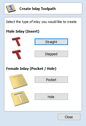
The Inlay toolpath functionality can be used to calculate either profile or pocketing toolpaths with automatic compensation for the tool radius; this allows the cut-out parts to fit into the corresponding cavities. This is a great feature for creating decorative woodwork and is also particularly useful for sign makers for creating inlayed letters and graphics.
How Inlays Work
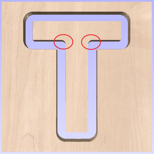
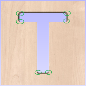
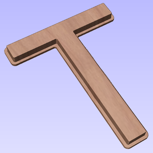
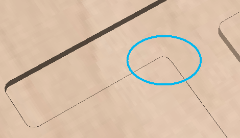
When using a CNC machine to cut out shapes then the tool will always leave a radius on any internal corner. When cutting holes or pockets the tool conversely leaves a radius on the external corners. If no changes are made to accommodate this then there would be no way to fit one part into the other. This is shown highlighted on the letter 'T' shown in the image below. On the left you can see the internal corners with a radius on the part being cut out (highlighted with red ovals). On the right you can see the radiused external corners on the hole (highlighted with green ovals). As you can envisage trying to slot the 'T' into the hole would not work as it is the proverbial square peg in a round hole!
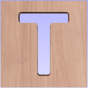
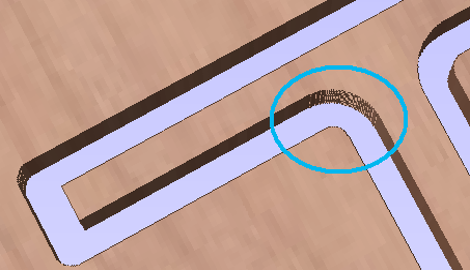
It is not possible to avoid the added radius as it is formed by the tool size and shape. The Inlay function though, will create toolpaths which take the tool radius into account and compensate for it by rounding off the sharp corners so the resulting parts will fit together. This can be seen in the images shown below where the same letter has been cut using the Inlay toolpaths, you can see all corners (internal and external) now have the same radius so they will slot together

When creating an Inlay toolpath the radius is automatically compensated for, so it is very important to make sure you specify the same tool for both parts of any inlay (male and female). If you do not do this the Inlay will not fit together.
If creating a Pocket then the main Tool (the finish tool) not the larger (clearance) tool should be the same as the one as used for creating the Male Inlay.
Note
You must use the same tool for both parts of an inlay for the resulting parts to fit together correctly.
Male Inlay (Insert)
Straight
This option is for cutting out straight sided parts to act as the inserted piece of the inlay. It uses a variation on the Profile toolpath which will automatically round the external corners of the part to allow for the radius of the tool being used. All the standard Profile options are available in this form except there is no option to Profile Inside or On as this does not apply to this inlay type as it has to cut outside of the vector. The other standard options not available are the ability to add sharp Corners or set a Last Pass as again these would not apply to this application. The image below shows how the external corners are rounded based on the tool radius being used.
Stepped
This option is for cutting out stepped sided parts to act as the inserted piece of the inlay. This style of inlay is typically used for what are referred to as 'Push Through' letters and shapes. These are parts which are inserted from the back and use the step as a shelf to invisibly mount them to the back of a sign. As with the Straight Inlay option it uses a variation on the Profile toolpath with the addition of the ability to specify a Step Depth and Step Width.
As the diagram shows in the form, the Step Depth is the vertical height of the step from the Start Depth down, the Step Width is how far from the edge of the original vector the part will be cut out (creating the step).
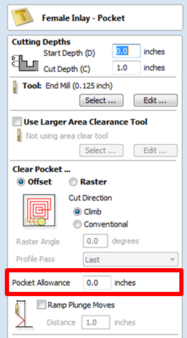
Female Inlay (Pocket / Hole)
This option is selected for cutting out a Pocket to act as the cavity for the corresponding Male shape to inlay into. It uses the same options as the standard Pocket style toolpath including the new option where you can use a larger and smaller tool to clear the pocket (smaller tool size should match that used for the Male Inlay). In order to make it work as an inlay pocket any internal corners will be rounded based on the tool radius to allow the male parts to fit into them (shown in the image below).
As has been previously discussed it is common to leave an allowance on one or both sides of the inlay, typically when working with letters the allowance would be left on the Pocket so the size and shape of the lettering itself is not affected any more than necessary.
Hole
This option is for cutting out a Hole to act as the cavity for the corresponding Male shape to inlay through. The standard Profile options are available for Female Hole Inlays except there is no option to Profile Outside or On as this does not apply to this toolpath type and this option does not allow the use of the Corner options as these are also inapplicable to this type of toolpath. In order to make it work as an inlay, any internal corners will be rounded based on the tool radius to allow the male parts to fit into them (shown in the image below).
Setting Inlay Allowances
Although the radius of the tool is compensated for when using the inlay tool, this in itself will almost always not be enough to ensure the two parts will fit together correctly. The parts will be exactly the same size and so would not fit together without a lot of force which would damage the part or without some kind of post-CNC hand work. Cutting the parts exactly the same size also does not allow for any kind of finish to be applied to either side.
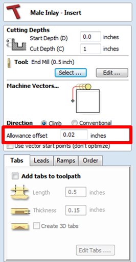
To enable the parts to fit extra material either needs to be cut from the Male side, the Female side or in some applications both. This additional distance is added using the option in the toolpath form to add an Allowance. On the toolpaths which are based on a Profile then this is done with the Allowance Offset (Shown in the image below left - highlighted in red). For Pocket style toolpaths use the Pocket Allowance, (shown in the image below right highlighted in red). When a value is entered it will overcut the selected shape by this distance, this will reduce the size for male parts and increase the hole/pocket for female parts.
The size of the Allowance required will depend on the type of material (how much it may expand or contract between being cut and inlayed), the accuracy of your tooling, the accuracy of your machine and finally any finish you are planning to add to the finished parts (such as paint or varnish which will have a thickness). In most situations where no finish is being applied before the parts are inlayed then an allowance of 0.01 inches (0.25mm) or 0.02 inches (0.5mm) will be sufficient. If you are not sure what value to use then you should experiment with this on a test part to get the correct sizes for your particular setup and application.
In the majority of cases the Allowance is applied to the Female side of the inlay as it is typical to not want to alter the actual vector shapes (the Male side) any more than is required for the tool radius. This means the Hole or Pocket will be cut over-sized to provide the additional allowance for the parts to fit.
Position and Selection Properties
Safe Z
The height above the job at which it is safe to move the cutter at rapid / max feed rate. This dimension can be changed by opening the Material Setup form.
Home Position
Position from and to that the tool will travel before and after machining. This dimension can be changed by opening the Material Setup form.
Project toolpath onto 3D Model
This option is only available if a 3D model has been defined. If this option is checked, ✓ after the toolpath has been calculated, it will be projected (or 'dropped') down in Z onto the surface of the 3D model. The depth of the original toolpath below the surface of the material will be used as the projected depth below the surface of the model.
Note:
When a toolpath is projected onto the 3D model, its depth is limited so that it does not exceed the bottom of the material.
Vector Selection
This area of the toolpath page allows you to automatically select vectors to machine using the vector's properties or position. It is also the method by which you can create Toolpath Templates to re-use your toolpath settings on similar projects in the future. For more information, see the sections Vector Selector and Advanced Toolpath Templates.
Name
The name of the toolpath can be entered or the default name can be used.