Drilling Toolpath
Drilling Toolpath Lesson for members of the Vectric Master Training Course:

Vectric Documentation:
Drilling Toolpaths
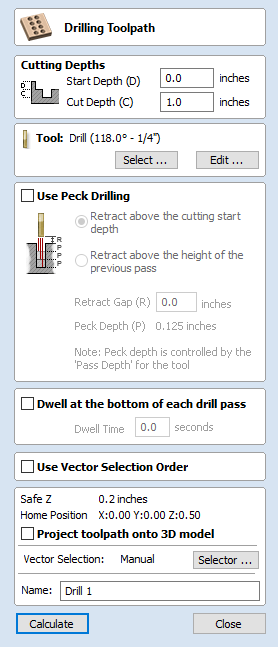
Drilling allows the centers of selected closed vectors to be drilled to a specified depth. The Tool Database includes an option to specify the Drill diameter and cutting parameters.
Cutting Depths
Start Depth (D)
This specifies the depth at which the toolpath is calculated from.
When cutting directly into the surface of a job the Start Depth will often be 0. If machining into the bottom of an existing pocket or 3D region, the depth needs be entered.
Cut Depth (C)
The depth of the toolpath relative to the Start Depth.
Tool
Clicking the Select button opens the Tool Database from which the required tool can be selected. See the section on the Tool Database for more information on this.
Clicking the Edit button opens the Edit Tool form which allows the cutting parameters for the selected tool to be modified, without changing the master information in the database. Hovering the mouse cursor over the tool name will display a tool tip indicating where in the Tool Database the tool was selected from.
Peck Drilling
When the option Use Peck Drilling is selected, the drill will cut to the Pass Depth set in the Tool Database for the selected Drill. It will then retract to the Retract Gap according to the retract option selected (see below), before drilling to the next depth, incremented by an additional Pass Depth. This cycle is repeated until the hole is drilled to the required depth. The retract moves are used to remove any build-up of material from the hole to help with overheating and breakage. If the Pass Depth is greater than the required Cut Depth, the hole will be drilled in a single cycle. However, if a Cut Depth of 1 inch with a Pass Depth of 0.25 inch is used the hole will be drilled in 4 cycles.
Retract above cutting start
This option will cause the tool to retract fully out of the drill hole after each peck drill plunge. This is beneficial for clearing swarf/chips completely from the drill hole during the drill cycle. With this option selected the Retract Gap value (R) is the fixed distance above the start cut depth. Thus the total retract and plunge distances for each peck drill cycle will increase as the hole deepens and this will generally result in longer machining times.
Retract above the height of the previous pass
Instead of fully retracting out of the drill hole, it is also possible to retract to a height relative to the previous cut depth. This strategy typically requires a shorter set of plunges and retracts over the course of a peck drill toolpath because they will be constant for each peck drill cycle, regardless of the drill hole depth. However, it will not necessarily clear swarf/chips completely from the drill hole. With this option selected the Retract Gap value (R) is the relative distance above the height of the previous peck drill pass.
Dwell at the bottom of each drill pass
With this option checked, ✓ the Dwell Time value is used pause the drill at the bottom of each peck drill pass before retracting. The dwell time value is measured in seconds.
Note
To make use of this feature your Post-Processor must support the Dwell section and may require updating.
Position and Selection Properties
Safe Z
The height above the job at which it is safe to move the cutter at rapid / max feed rate. This dimension can be changed by opening the Material Setup form.
Home Position
Position from and to that the tool will travel before and after machining. This dimension can be changed by opening the Material Setup form.
Project toolpath onto 3D Model
This option is only available if a 3D model has been defined. If this option is checked, ✓ after the toolpath has been calculated, it will be projected (or 'dropped') down in Z onto the surface of the 3D model. The depth of the original toolpath below the surface of the material will be used as the projected depth below the surface of the model.
Note:
When a toolpath is projected onto the 3D model, its depth is limited so that it does not exceed the bottom of the material.
Vector Selection
This area of the toolpath page allows you to automatically select vectors to machine using the vector's properties or position. It is also the method by which you can create Toolpath Templates to re-use your toolpath settings on similar projects in the future. For more information, see the sections Vector Selector and Advanced Toolpath Templates.
Name
The name of the toolpath can be entered or the default name can be used.
Click here for more live lesson replays on Drilling Toolpath