3D Roughing Toolpath
3D Roughing Toolpath Lesson for members of the Vectric Master Training Course:

Vectric Documentation:
3D Rough Toolpath
Rough Machining is used when carving 3D parts to clear away excess material when the part is too deep for the finishing tool to cut in a single pass.
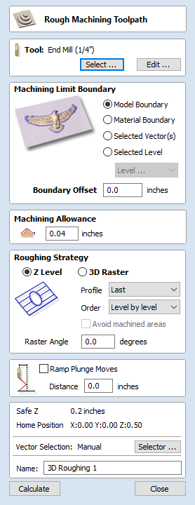
Clicking on this icon opens the toolpath form shown to the right; the functions available within this are described below.
Tool
Clicking the Select button opens the Tool Database from which the required tool can be selected. See the section on the Tool Database for more information on this.
Clicking the Edit button opens the Edit Tool form which allows the cutting parameters for the selected tool to be modified, without changing the master information in the database. Hovering the mouse cursor over the tool name will display a tool tip indicating where in the Tool Database the tool was selected from.
Machining Limit Boundary
The machining limit boundary is the area in which the tool will operate. There are several options:
Model Boundary The combined boundaries of all the components in this job are used. This is the area of the composite model which has components on it. Note: this is not the boundary of the selected models.
Material Boundary The boundary of the entire material block is used.
Selected Vector(s) Selected vectors are used as the machining boundary.
Selected Level The combined boundaries of all the components on the specified level. This is similar to Model Boundary, but only specific to the named level.
Boundary Offset
If you are machining a raised object, often the tool will not fully machine down the edge. This field is used to specify an offset to the selected machining boundary to increase its size to allow the tool to go past the actual edge if needed.
Note
The tool tip (rather than the cutting side) will not leave the machining boundary. This is to help ensure that roughing removes enough material on machining boundaries.
Machining Allowance
The machining allowance is a virtual thickness which is added to the 3D model when the Roughing Toolpath is calculated. This ensures that the toolpath leaves some extra material on the roughed part.
This is beneficial for two main reasons, the first is that when roughing it tends to be done with relatively large tool and aggressive cuts and so is more prone (depending on the material) to chip, this skin helps to prevent the chipping affect the finished surface. The second reason is that most tools cut well when they are constantly removing material. Therefore leaving an allowance of material on ensures that there is always at least some material for the finishing toolpath to remove.
Roughing Strategy
The roughing strategy determines the process the toolpath will take to remove the desired material
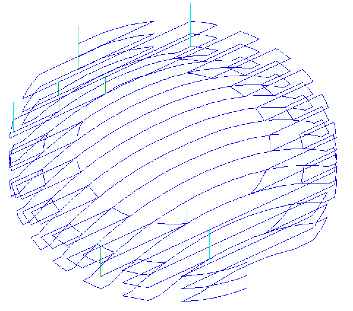
Z Level Strategy
Z Level Roughing essentially uses a series of 2D Pocket toolpaths which take into account the 3D model and hog-out the material around it within the specified boundary.
The first setting is the choice of Profile, this controls whether each level has a profile cut around its boundary or not and if so whether it cuts before the raster or after it. First does the profile before the Raster on each level, Last does the profile cut after the raster and None eliminates the Profile cut leaving only the raster pattern. These choices depend a lot on the material and tooling being used. For example, more brittle material may benefit from the profile first option to reduce chipping.
The second setting is the choice of Order. The Z Level can be performed in Level by level manner. This means to generate a complete pass at a given depth over the whole model, before advancing to the next level. This is the default option.
The user can also select Depth-first. In this case if at a given depth the model consists of separate regions, the generated toolpath will generate all passes at increasing depths over such region. Then it will advance to another such region.
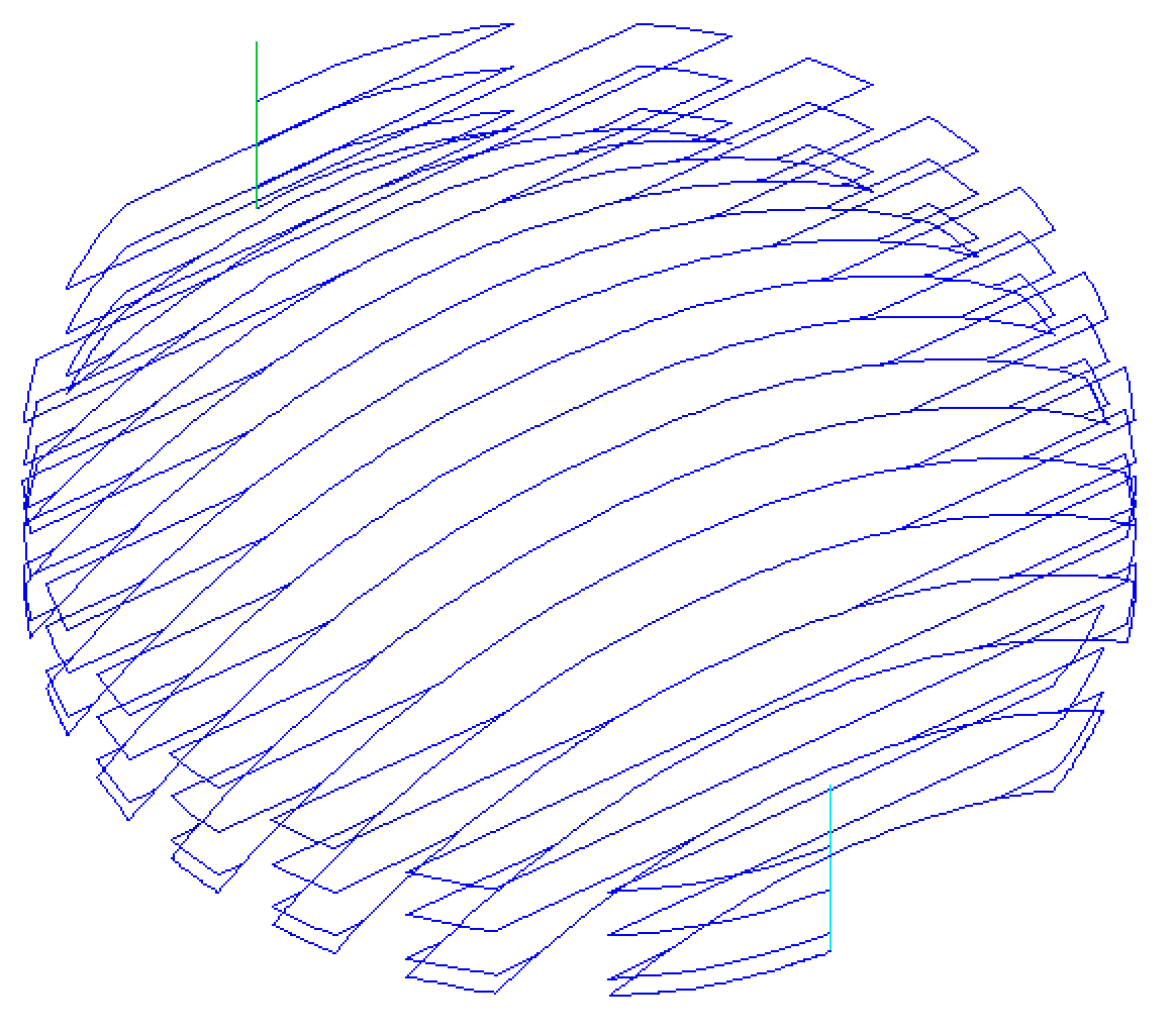
3D Raster Strategy
The 3D Raster strategy is a 3D cut which passes over the whole model. This will leave a more even amount of material for the finish cut to remove but depending on the depth and style of the part it may take significantly longer to run. In shallower parts where the roughing is only taking one or two passes then this may be a better choice. For deeper parts then typically the Z Level rouging is a more efficient.
Raster direction
This option allows to define the main cutting direction.
Reverse step direction
By default, when using raster direction Along X the tool will move from one raster line to another from bottom to top. In case of raster direction Along Y the tool will move from right to left. This option allows to reverse that stepover direction.
Note
This option is currently only available for Z Level strategy.
Avoid Machined Areas
This option means that if an area has been machined by a previous pass of the toolpath it will not be machined by any later passes. This can mean the toolpath is quicker to machine
Note
It is not guaranteed that the toolpath is quicker. It might seem that skipping any previously machined areas should be quicker, but if this introduces more retracts and slows the machine due to extra acceleration and decelerations, then the final result could be slower.
Ramp Plunge Moves
The cutter can be ramped over a distance into the pocket instead of plunging vertically. This approach reduces heat build-up that damages the cutter and also reduces the load on the spindle and z axis bearings
Position and Selection Properties
Safe Z
The height above the job at which it is safe to move the cutter at rapid / max feed rate. This dimension can be changed by opening the Material Setup form.
Home Position
Position from and to that the tool will travel before and after machining. This dimension can be changed by opening the Material Setup form.
Vector Selection
This area of the toolpath page allows you to automatically select vectors to machine using the vector's properties or position. It is also the method by which you can create Toolpath Templates to re-use your toolpath settings on similar projects in the future. For more information, see the sections Vector Selector and Advanced Toolpath Templates.
Click here for more live lesson replays on 3D Roughing Toolpath