Two Rail Sweep
Two Rail Sweep Lesson for members of the Vectric Master Training Course:

Vectric Documentation:
Two Rail Sweep
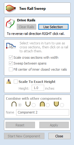
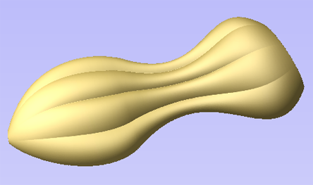
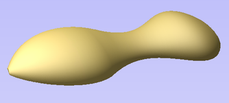
Two Rail Sweep uses a combination of vectors to define a swept 3D Component. The shape is based on two drive rails which can be open or closed vectors and multiple cross sections which are positioned on the drive rails and have to be created using open vectors.
Drive Rail Selection
The first stage of using this tool is to select the vectors which will represent the Drive Rails. From the 2D View use the mouse to select two open or closed vectors then click the Use Selection button.
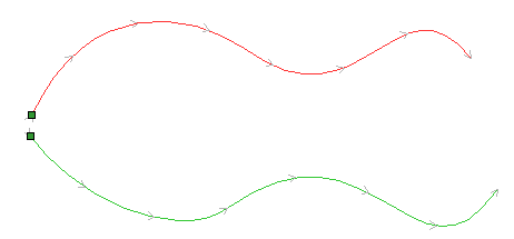
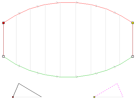
In the 2D view your rail vectors will now be colored red (first selected vector) and green (second selected vectors) and show a square green start node indicating the start point of each rail and arrow markers along its length to show the direction the shape will be swept.
The start point and direction may not be what you intended. To change the direction, right-click with the cursor on the drive rail you want to edit and select Reverse Rail from the context sensitive menu, you will now see the arrows on the drive rail change direction.
You can also change the order the rails were selected by clicking on Swap Rail Order this will swap so the red rail becomes green and green becomes red, doing this will cause the cross-sections to hang in the opposite direction. On a closed vector you can change the start point by placing the cursor over an existing node in the drive-rail vector, right-clicking and selecting Make Start Point or you can right-click anywhere on the vector and select Insert Start Point to create a new node which will become the start point.
The Clear Rails button on the form can be used at any time to empty your current selection. This will delete your current shape and deselect all the drive rails and cross section vectors. This can be used if you do not want to create a Component before you exit the form or if you want to select new vectors in the 2D view to use as the drive rail for your shape.
Cross Section Selection
After you have chosen your drive rails the next step is to select one or more cross-section vectors to sweep along those vectors to form a 3D shape. In order for vectors to be used as valid cross-section shapes, they must be open.
Select a vector that you wish to use as a cross-section in the 2D View by left clicking on it with the mouse.
If you are using just a single cross section then you just need to make sure it is selected and then can proceed with the other settings in the form and calculate your shape. If you want to edit cross section positions or add more than one cross section then you will need to attach them to the drive rails.
Select a vector that you wish to use as a cross-section in the 2D View by left clicking on it with the mouse. Now click on the drive rail to attach the cross-section to that vector.
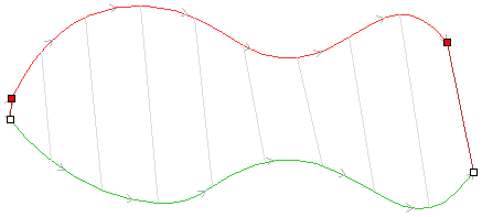
As you move the mouse over a selected drive rail it will indicate with a check mark ✓ that it is a valid place to add the cross section. Once a cross-section has been successfully attached to your drive rail, the 2D view will show a preview using line markers to indicate how the cross section will be positioned when it is extruded.
Two Cross-Sections are always created when you attach the first cross-section to the drive rail - one across the start nodes of each vector and one across the ends. The intermediate lines along the entire length of the rails indicate how the shape will flow between the defined cross sections. You can click the Apply button to create your 3D swept shape.

Using multiple cross-sections
It is possible to extrude between multiple cross section vectors along a drive rail blending from one vector shape to another.
Adding Cross-Sections
To add a new Cross-Section to an existing extrusion, simply select an open vector in the 2D View that you wish to use as a cross-section. With the vector selected, click on the point along the rail to which you wish it to be attached. A new Cross-Section will be inserted at this point and automatically attached to the second rail. On applying the change, the resulting 3D sweep will blend between all the defined Cross-Sections along the rail.
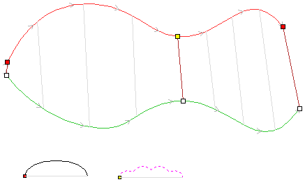
Note
To help differentiate which cross section is being used at each location the software will indicate a colored node at one end of each cross section and place the same colored node on the preview position. This node also indicates the direction the cross section is being 'hung' across the rails. The same cross section vector can be used in multiple locations along the drive rail.
Connecting Rail Nodes
By default, Aspire sweeps the cross-section along the drive rails connecting points at the same proportional distance along each rail's length. So, for example, the positions halfway or three-quarters of the way along each drive rail will be connected by the cross section in the resulting 3D shape.
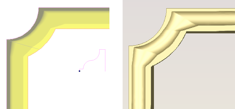
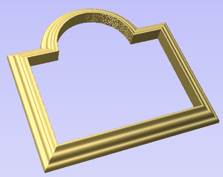
As the images above show, when the matching proportional positions along each rail do not match the appropriate features of the shape it can produce undesirable results. In this example the corners of the frame design are at different proportional positions along each rail and so the two-rail sweep does not connect the corners. Instead the cross-section appears stretched around the frame, as it is used to connect other points that do match in their proportional distance along each rail.
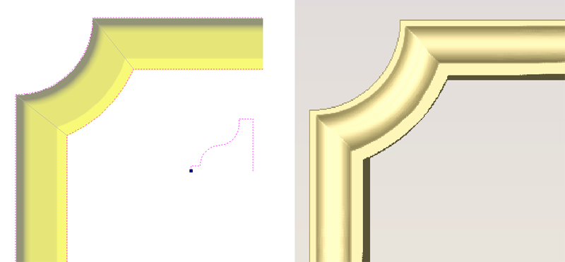
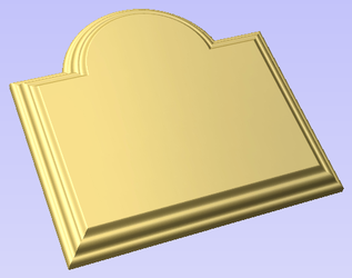
To resolve this, the software allows you to force the connection of pairs of points along the drive rails. This can either be done manually by inserting and re-positioning the cross-sections across the corners (see sections below for more information on this), or if both the drive rails have the same number of nodes it can be done automatically after you have added the first cross section by right-clicking on the first cross section preview position and selecting Add To All Rail Nodes. This will add that same cross section to every pair of nodes on each drive rail. When the cross section positions are set up correctly then Aspire will sweep the shape between each cross section location and create clean corners as shown in the images below.
Removing Cross-Sections
To remove a Cross-Section, position the cursor over the cross section and press the RIGHT button on the mouse. Select the option to Delete Cross Section from the menu.
You can remove all the Cross-Sections on the drive rails by positioning the mouse arrow over a part of the curve that does not contain a cross section. This will bring up a different context sensitive menu and you can select the options to Remove All Cross Sections.
Altering Existing Cross-Sections
Existing cross-sections can be re-positioned on the drive rail. To do this click on the nodes at either end of the cross section preview in the 2D View (the ones on the rails), hold the mouse down and drag the node to a new position on the curve, let go of the mouse button to release that end of the cross section in its new position. You should make sure you do not drag a cross section past another existing cross section on the shape. If you need to move cross sections out of their current order then you should remove the existing cross section and insert the same shape at the new position so the shape can be created correctly. Any of your current cross-sections can be replaced by selecting a different open vector, moving the mouse over the end node of the cross section you want to change and clicking on it. The node color indicated on the cross section preview position on the curve will change to indicate which vector is now being used at that point in the shape.
Controlling the Swept Shape
There are check boxes in the form that allow you to Scale cross sections with width, Sweep between spans, and Fill center of inner closed vector rails. The Smooth option under the right-click menu allows you to control different aspects of the shape you create with the selected set of vectors.
Scale cross sections with width
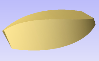
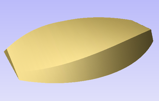
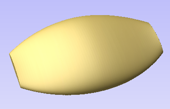
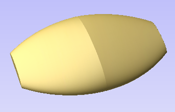
As the cross sections are extruded along the rails the user can either choose to retain the exact shape and height of the cross sections or for a more natural look the Scale cross sections with width option can be checked ✓. This will alter the height of the cross section in proportion to the distance between the rails. This means that as the rails get further apart the shape gets higher and as they get closer together the shape gets lower. The image below left shows the result if this option is un-checked and below right with it checked ✓.
Sweep between spans
This option only becomes active if all selected cross section vectors have the same number of spans and nodes. When checked ✓ it will ensure that as the shape is extruded that it goes from a particular node/span in one cross section to the same node/span on the next cross section. In certain shapes this can give the user more control over the way the shape flows.
Fill center of inner closed vector rails
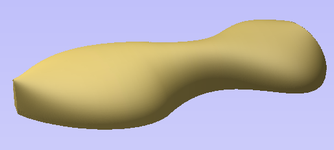
If you are sweeping two closed vectors to form a border or boundary shape, you can have Aspire automatically find the height that the cross-section forms on the inner boundary and then fill the shape to this height. To activate this check ✓ the Fill center of inner closed vector rails option in the form. This tool is perfect for sweep decorative bases, plaques or stands. Below left you can see a shape created with this option off and on the right an option with it activated.
Smooth transition through the Cross Sections
As the swept shape passes through each cross section the default is for it to flow smoothly through the profile. This can be edited by right-clicking over the end node of the cross-section and unchecking the Smooth option.
Scale to Exact Height
Checking ✓ this option scales the shape calculated so its maximum height is the value entered in the Height area of the form.
Common Modeling Options
All of the main modeling tools in the software use a common set of commands to assign a name and combine mode to the component being created along with options to apply the settings in the form, reset the shape, start creating a new component and close to exit the function.
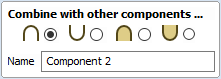
Combine with other components...
This section includes options to allow you to name your Component and control the way it will be combined with other objects in the Component Tree.
Reset
Clicking the Reset button will remove the current shape, doing this before you Close the form will ensure that a component is not created from the current selection. Clicking this does retain the current set of selected vectors or Components.
Apply
Clicking the Apply button will create a shape based on the settings you have chosen. You can continue making edits to the component by choosing different parameters within the form and hitting Apply to update it.
Start New Component
Clicking the Start New Component button will save the state of the component that has been created, deselect all components/vectors and start the creation process again on a new component. The values and options within the form will be retained in this case until you Close it.
Close
Clicking the Close button will close the form returning to the Modeling Tab icons and the updated Component Tree, reflecting any changes that you have made. If you wanted to remove the shape you just created then you can hit the Undo icon or use the keyboard shortcut to undo, CTRL+Z.