Slice Model
Slice Model Lesson for members of the Vectric Master Training Course:

Vectric Documentation:
Slice Model
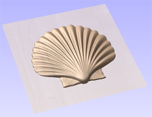
The slicing feature allows the user to divide the Composite Model into Z-Slices each of which will become a Component. This is for customers who need to cut a part which exceeds the Z depth of their machine gantry, the cutting length of their tools or the thickness of the material they are using. Once the slices have been cut on the CNC then they can be re-assembled to make the finished full depth part.
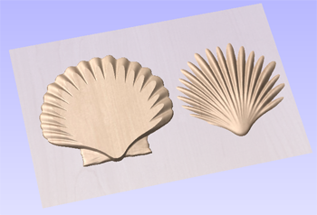
When this function is executed each slice will become a Component in the Component Tree and can then be moved into position and have toolpaths calculated on it. An example of this is shown in the images below, on the left it shows a scallop shell component that is 3 inches thick, the image below right shows this divided into two separate components, each a 1.5 inch slice of the original.
Note
Before using the Slice model command it is important to make sure that you hide any components that you do not wish to include in the operation.
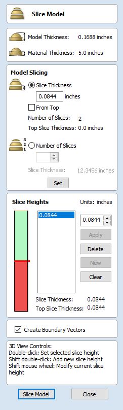
When the icon is clicked the Slice Model form will appear. This can be used to control the number and thickness of slices which will be created. At the top of the form it will display some reference information showing the thickness of the current Composite Model and also the currently defined Material Thickness (for machining).
Model Slicing
The Model Slicing section can be used to set up the initial slices which can later be customized in the Slice Height section.
There are two ways to set up the initial slicing: by setting a standard slice thickness or by setting a fixed number of slices.
Slice Thickness
Checking this option allows you to specify the default slice thickness. You can choose if you want to slice from the top down or bottom up using the From Top checkbox. Each slice is will be the specified thickness, except for the final slice which will be whatever height remains after all the other slices have been taken. If From Top is checked then the final and potenitally thinner slice will be at the bottom. If From Top is uncheched then the final and potentially thinner slice will be at the top.
Number of Slices
Checking ✓ this option will divide the model into a specific number of slices. The slice thickness will be determined by the Composite Model thickness divided by the Number of Slices defined. This may be a good option to use if the specific slice thickness is not important (for instance if it does not relate to material thickness).
Example
If the Composite Model is 3.96 inches thick and you define 3 Slices then the software will create 3 Component slices each 1.32 inches thick.
Create Boundary Vectors
Checking ✓ this option will cause the slicer to create vector boundaries for each slice. These can be useful for defining the subsequent machining regions required to cut each part. The boundary vectors will be placed on the same layer in the 2D View as the component preview for their associated model slice.
Slice Model
Clicking Slice Model will apply the choices made in the form and create the Components which represent each slice of the Composite Model.
Note
The Component Tree will retain a copy of the original Components in the part as well as the new Slice Components. This may result in a very thick looking model as all the slices will be added to the original shapes. At this point you can delete, undraw or move Components before proceeding with any additional operations.
Close
Clicking Close will close the Slice Model form without completing the operation.
Slice Heights
The Slice Heights section controls the specific details of each individual slice height. It also allows customization of the number of slices.
There are two many parts to the slice height control:
- The height bar which gives a visual indication of the slice heights
- The slice list which lists the slice heights using their z value
The slice height section is for editing the values at which the model is sliced and not the slices themselves.
Controlling Slice Thickness
A specific slice height can be controlled by selecting it from the slice list, updating the value and clicking Apply.
Updating the height of a specific slice might potentially adjust the thickness of the surrounding slices
Add New Slices
Additional slices can be added by either:
- Entering a specifc z height for the slice and selecting apply; or
- Double clicking on the height bar at a particular location
Double click to add slice
Removing Slices
To remove a slice height select it from the list and press the Delete button. Deleting a slice height will merge the surrounding slices into one slice.
3D View
When the slicing tool is open then the 3D view gives a visualisation of the results of the slicing. If a slice height is selected then:
- Red areas show which are included in this slice
- Green areas indicate that the component is above the slice height and so these will be sliced flat.
- The slice will occur between the Red and the green areas.
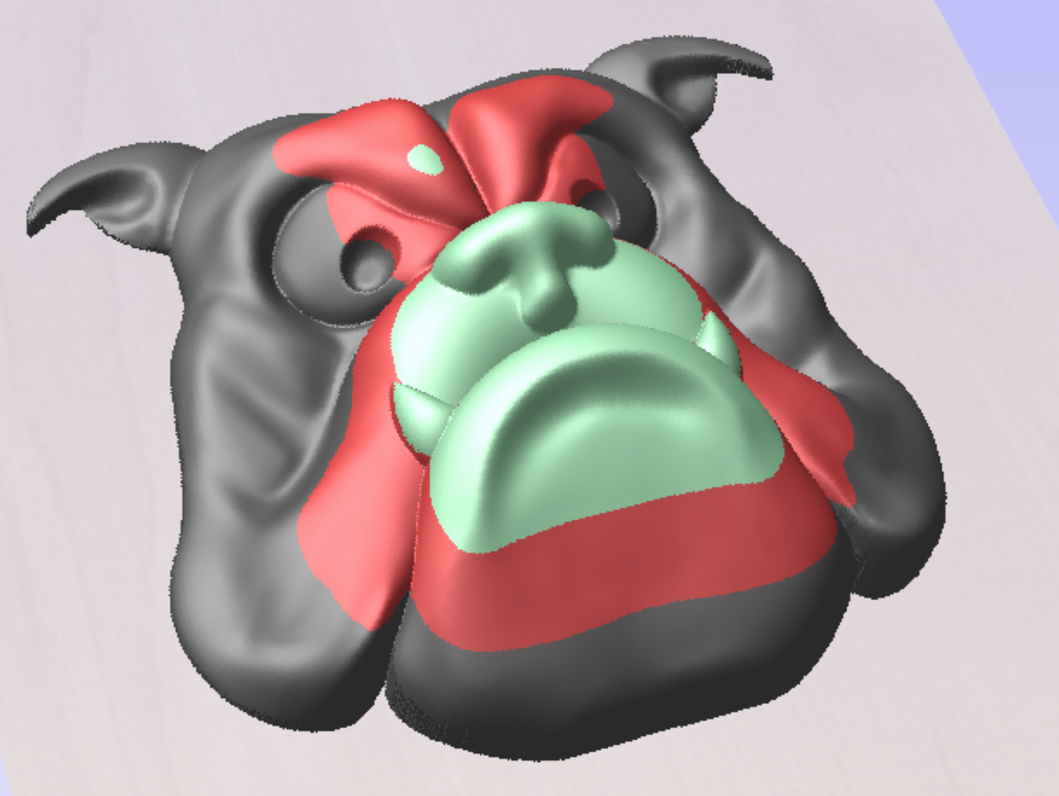
Green areas are above the slice, red areas are the current slice.
You can also manuipulate the slices within the 3D View
- Double clicking on the model will change the value of the active slice height to be equal to the clicked height.
- Shift + Double Click will insert a new slice height at the clicked height.
- Shift + Mousewheel up/down will raise/lower the actice slice height by a small amount allowing you to tweak the thickness to remove thin slices.