Texture Toolpath
Texture Toolpath Lesson for members of the Vectric Master Training Course:

Vectric Documentation:
Texture Toolpath
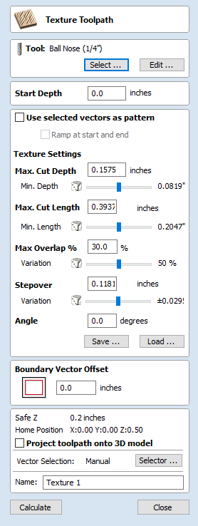
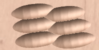
The 3D Texture Machining functionality uses a specialized toolpath algorithm and the shape of the tool to generate a textured finish on the part.
Tool
Clicking the Select button opens the Tool Database from which the required tool can be selected. See the section on the Tool Database for more information on this.
Clicking the Edit button opens the Edit Tool form which allows the cutting parameters for the selected tool to be modified, without changing the master information in the database. Hovering the mouse cursor over the tool name will display a tool tip indicating where in the Tool Database the tool was selected from.
Texture Settings
Use selected vectors as pattern
By default this option is unchecked and the texture form will generate a random texture pattern using any selected vectors as a clipping area. If this option is checked, ✓ the currently selected vectors will be used as the pattern for the texture and the only options available will be 'max. Cut Depth' and 'min. Depth' to control the depth of the cuts along the selected vectors.
Ramp at start and end
This option is only available when using selected vectors as patterns. If this option is checked ✓ each of the selected contours is cut using a fluting move, otherwise each of the contours is cut with a regular profile move. The resulting textures may look very different because of this small change.
Max. Cut Depth
The maximum depth any of the carved scallops will be machined to and is specified in the job units.
Min. Depth
Using the slider this is specified as a percentage (%) of the Max. Cut Depth and controls the minimum depth any of the scallops will be machined to.
Note
For example, with a Max Cut Depth = 0.200 inches and a Min Cut Depth of 0.050 inches, the depth of the carved scallops will range randomly between 0.200 inches and 0.050 inches.
Max. Cut Length
Specifies the maximum length for any of the carved grooves and is specified in the job units.
Min Length
Using the Slider this is specified as a percentage of the Max Cut Length and controls the minimum length any of the carved grooves.
Max. Overlap %
The percentage (%) of the Max Cut Length that each scallop is allowed to overlap the adjacent scallop running along the cutting direction. Where, 1% will result in almost zero overlap of adjacent scallops 50% will result in some of the scallops being machined half way over the adjacent scallop.
Variation
Using the slider this is specified as a percentage of the Max Overlap. Overlap variation of 100% = the Max Overlap and random pattern Overlap variation of 1% = No Overlap and an almost constant pattern.
Stepover
The distance between each parallel set of lines of carved scallops.
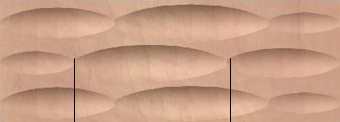
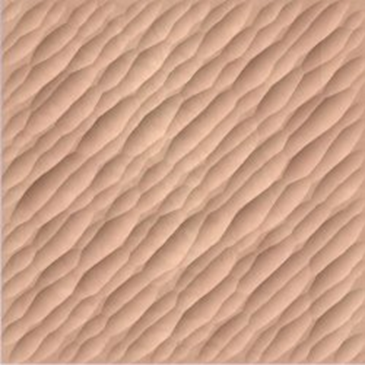
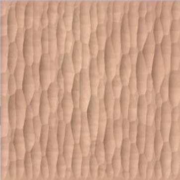
Angle
The direction the texture is machined across the surface, an angle of zero is parallel to the X axis, examples of setting the angle to 45 and 90° can be seen below.
Boundary Vector Offset
If you enter a value in this field, the texturing will be offset from the boundary by the specified amount. If you are texturing in a recess, you should enter a value here up to the radius of the tool to avoid the walls of the recess being damaged by the tool.
Position and Selection Properties
Safe Z
The height above the job at which it is safe to move the cutter at rapid / max feed rate. This dimension can be changed by opening the Material Setup form.
Home Position
Position from and to that the tool will travel before and after machining. This dimension can be changed by opening the Material Setup form.
Project toolpath onto 3D Model
This option is only available if a 3D model has been defined. If this option is checked, ✓ after the toolpath has been calculated, it will be projected (or 'dropped') down in Z onto the surface of the 3D model. The depth of the original toolpath below the surface of the material will be used as the projected depth below the surface of the model.
Note:
When a toolpath is projected onto the 3D model, its depth is limited so that it does not exceed the bottom of the material.
Vector Selection
This area of the toolpath page allows you to automatically select vectors to machine using the vector's properties or position. It is also the method by which you can create Toolpath Templates to re-use your toolpath settings on similar projects in the future. For more information, see the sections Vector Selector and Advanced Toolpath Templates.
Name
The name of the toolpath can be entered or the default name can be used.
Click here for more live lesson replays on Texture Toolpaths